
A woodworking plan can look perfectly reasonable—right up until the lumber is on your bench.
The finished photograph is clear enough. You can see the table, cabinet, bookshelf or workbench you want to build. Then you turn to the drawings and find yourself staring at arrows, dashed lines, fractions, abbreviations and a collection of flat rectangles that are somehow supposed to become that finished piece.
That is usually when the doubt arrives. Quietly at first.
If you misread one measurement, will every part that follows be wrong? Does that dashed line represent a hidden screw, a dado or the edge of another board? Are you looking at the front of the project or the back? And why does the plan call for a 2×4 when the board in your hand does not measure 2 inches by 4 inches?
The mistake most beginners make is trying to understand the entire plan in one pass. It is too much information arriving without hierarchy. Your eyes jump from the cut list to the diagrams, from the diagrams to the instructions, and back again. Nothing has settled into place.
The better approach is to read a woodworking plan in layers. First the finished object. Then the materials and components. Then the drawings, measurements, joints and assembly sequence. Once those layers begin speaking to one another, the page changes. What felt like code starts to feel like a map.
The Short Answer: How Do Beginners Understand Woodworking Plans?
To understand woodworking plans, begin with the finished project and work inward. Confirm its overall dimensions, examine every part of the plan package, identify the different drawing views, follow the written measurements, verify the actual lumber sizes, match the cut list to the diagrams, decode the joinery and rehearse the assembly order. Only then should you make the first cut.
The complete nine-step system looks like this:
- Study the finished project and its overall dimensions.
- Review every part of the plan package.
- Learn what each drawing view is showing you.
- Decode dimensions, fractions and scale.
- Verify the real sizes of lumber and sheet goods.
- Read and validate the cut list.
- Interpret symbols, joinery and hardware.
- Turn the instructions into a practical build sequence.
- Perform a final pre-cut audit.
You do not need to memorize the whole project. You only need to answer the right questions in the right order.
By the time you reach Step 9, every component should have an identity. You should know what it is, where it belongs, how it connects and when it enters the build.
Learn more: How to Read Woodworking Plans: A Beginner’s Guide to Symbols, Cut Lists and Diagrams
What a Woodworking Plan Is Really Trying to Tell You
A woodworking plan is more than a drawing with measurements scattered around it. It is a set of written and visual instructions describing the finished project, the parts inside it and the sequence that turns raw material into a working object.
A complete plan should tell you:
- What the finished project looks like
- How large it will be
- What materials and hardware it requires
- How many individual parts must be made
- What size each part should be
- How those parts connect
- Which tools and joints are required
- In what order the project should be assembled
You may see the terms woodworking plan, project plan, blueprint, working drawing and construction drawing. In a home workshop, the distinctions matter less than the quality of the information.
A beautiful sketch is not automatically a usable plan. Neither is a project photograph with three dimensions written beside it. If you cannot determine what to buy, what to cut, how the parts fit together and how large the finished piece will be, you are still looking at inspiration rather than reliable building instructions.
Recommended guide: How to Check Woodworking Plans for Mistakes Before You Cut Any Wood: The 15-Point Pre-Build Audit
The Parts That Make a Plan Buildable
| Plan element | What it contains | The question it answers |
|---|---|---|
| Project overview | Finished image, purpose and difficulty | What am I building? |
| Finished dimensions | Overall height, width and depth | Will it fit? |
| Materials list | Lumber, plywood and supplies | What must I buy? |
| Hardware list | Screws, hinges, slides, brackets and fasteners | What holds it together? |
| Tool list | Saws, drills, bits, jigs and clamps | Can I perform the required work? |
| Cut list | Quantity and dimensions of each wooden component | What parts must I make? |
| Construction drawings | Shape, position and orientation of the parts | Where does everything go? |
| Joinery details | Dados, rabbets, mortises, pocket holes and connections | How do the parts connect? |
| Assembly instructions | Ordered construction steps | What happens first, next and last? |
| Finishing notes | Sanding, staining, painting and protection | How should the surface be completed? |
Not every designer arranges this information in the same way. One plan may place the cut list on the first page. Another may introduce dimensions gradually inside the construction steps. Some rely heavily on exploded diagrams; others use photographs.
Your first job is not to judge the layout. It is to find the information and bring it into a sequence you can trust.
Step 1: Meet the Finished Project Before You Meet the Parts
Resist the urge to begin with the cut list.
Start with the main photograph, rendering or perspective drawing. Find the front of the project. Notice the top, sides and back. Look for doors, shelves, drawers, lids or anything that moves.
Now mentally separate the project into larger groups.
A basic table might contain:
- A tabletop
- Four legs
- Front and back aprons
- Two side aprons
- One or more stretchers
- Hardware connecting the top to the base
A cabinet may break into a carcass, face frame, back panel, shelves, doors, drawers and hardware.
This simple exercise gives every later measurement somewhere to belong. A 13-inch board is easier to understand when you already know the table needs two aprons between its front and back legs.
Find the Finished Dimensions
Locate the overall:
- Height
- Width
- Depth
These measurements describe the outside boundaries of the completed project. They also answer a question beginners sometimes ask too late: will this thing actually fit?
Measure the intended location. Then think beyond the empty space itself.
Check:
- Doorways, hallways and stairs
- Baseboards and trim
- Outlets, vents and radiators
- Uneven walls or floors
- Drawer and door clearance
- Walking space
- Nearby furniture
- The room required to sit or work comfortably
A cabinet can be built exactly to plan and still collide with a baseboard. A workbench can fit the wall but block an outlet. A table can look perfectly proportioned in isolation and feel enormous once chairs surround it.
The plan knows the project. It does not know your room.
Establish Front, Back, Left and Right
Orientation sounds elementary until four similar-looking parts require holes on four different faces.
Use the finished drawing to identify:
- Front and back
- Left and right
- Inside and outside faces
- Top and bottom edges
- Visible and concealed surfaces
- Grain direction
Then adopt a labeling system you will use throughout the build:
- FL: front left
- FR: front right
- BL: back left
- BR: back right
- IN: inside face
- OUT: outside face
- TOP: upper edge
Painter’s tape is ideal for temporary labels. A soft pencil also works on surfaces that will later be sanded.
A hole drilled in the right location on the wrong face is still wrong. Clear orientation prevents that kind of mistake before it becomes permanent.
Say the Project Out Loud
Before moving on, describe what you are building in plain language.
For example:
“This is a 24-inch-high side table with four legs, four aprons and a rectangular top. The top overhangs the base by one inch on every side. The aprons connect the legs, and the top is attached after the base is assembled.”
If you can explain the project that simply, you have created a mental frame for everything that follows.
Step 2: Find Out What the Plan Quietly Demands
Now gather every part of the plan package:
- Finished photographs or renderings
- Overall dimensions
- Materials list
- Hardware list
- Tool list
- Cut list
- Construction drawings
- Full-size templates
- Written instructions
- Finishing recommendations
- Legends, symbols and notes
Read through all of it before cutting anything.
This first reading is not about remembering each step. It is reconnaissance. You are looking for small sentences with large consequences.
Watch for notes such as:
- “Cut this component to fit after assembly.”
- “Make one left-hand and one right-hand part.”
- “Do not glue this joint.”
- “Drill these holes before attaching the panel.”
- “Orient the grain as shown.”
- “The final width depends on the actual plywood thickness.”
- “Sand the inside faces before glue-up.”
Instructions like these are easy to miss when attention is fixed on the large numbers in the diagrams.
Read the Materials List Beside the Drawings
The materials list describes the raw stock and supplies from which the project will be built. Depending on the design, it may include:
- Dimensional softwood
- Rough or surfaced hardwood
- Plywood
- MDF or particleboard
- Dowels or wooden plugs
- Screws, nails or bolts
- Hinges and drawer slides
- Adhesive
- Sandpaper
- Paint, stain or protective finish
Do not rush to the lumberyard as soon as you find the list. First, compare it with the cut list and drawings.
You are trying to discover what the project demands beneath the surface:
- Does the visible grain need to match?
- Are unusually wide boards required?
- Is a specific plywood thickness important?
- Does the design depend on knot-free stock?
- Will one board need to produce several identical parts?
- Does the project require extra material for milling or test cuts?
The amount printed on the page may be the theoretical minimum. Real lumber contains knots, checks, cracks, twist, cup and grain that refuses to cooperate. Saw kerfs and milling remove material too.
How much extra stock you need depends on the project and the quality of the boards available. Straightforward work made from clean dimensional lumber may require only a modest allowance. Furniture built from rough hardwood, especially when grain and color must match, may require considerably more.
For a closer look at species, grades, defects and stock selection, use this wood-buying guide.
Let the Tool List Reveal the Real Difficulty
A small project is not automatically a simple project.
A compact cabinet might require precise concealed-hinge holes. A modest tabletop may need long clamps and a reliable method for flattening the panel. A curved part may depend on a full-size template and a router bit you have never used.
Sort the required tools into three groups:
- Tools you own and know how to use
- Tools you can safely borrow, rent or replace with another method
- Tools or operations that place the project beyond your current setup
There is often more than one way to perform an operation. A table saw is convenient for ripping boards, but a circular saw used with a secure guide can handle many of the same basic cuts. A planer can dimension rough stock quickly, but surfaced lumber may remove the need for one.
The real question is not whether your workshop resembles the designer’s. It is whether you have a safe, accurate method for every operation the plan requires.
If you are still building your workshop gradually, this guide to the best woodworking tools for beginners will help separate essential equipment from the tools that can wait.
Step 3: Stop Seeing Flat Drawings—Start Seeing the Object
A woodworking plan takes a three-dimensional project and flattens it into several two-dimensional views. At first, those views can feel disconnected. One page appears to show a rectangle. Another shows a collection of lines. A third seems to pull the entire project apart.
Each view has a job.
Once you know what information to expect from it, the drawing becomes much easier to read.
Perspective or Isometric View
A perspective or isometric drawing shows several sides of the project at once. It looks more like the object you would see in the room.
Use it to understand:
- Overall form
- Proportions
- Part orientation
- The relationship between major assemblies
- Which surfaces remain visible
This is usually the easiest view for developing a mental picture, but it may not carry every precise dimension.
Front View
The front view looks straight at the project’s front face.
It often reveals:
- Overall height and width
- Leg spacing
- Rail and stile positions
- Door and drawer placement
- Vertical and horizontal alignment
- Visible gaps and reveals
What it usually does not show clearly is depth. For that, you need another view.
Side View
The side view shows height and depth.
It can clarify:
- Front and rear overhangs
- Side-apron positions
- Shelf depth
- Angled legs
- Seat or backrest angles
- Hardware placement
- Features hidden in the front view
A part that looks like a simple line from the front may reveal its full width and position from the side.
Top View
A top view looks down on the project.
Use it to understand:
- Width and depth
- Tabletop overhang
- Leg positions
- Shelf layouts
- Internal dividers
- Corner relationships
- Miters
- Alignment between upper and lower assemblies
For tables, cabinets and workbenches, the top view often resolves spacing questions that remain ambiguous elsewhere.
Exploded View
An exploded drawing shows the project pulled apart while preserving the relationship between its components.
The pieces may appear to float. They have not been scattered randomly. The space between them exposes information that would disappear in the completed assembly.
An exploded view can show:
- Which parts touch
- How components align
- The direction of assembly
- Where fasteners enter
- Which pieces sit inside or outside others
- How joints come together
- A likely order for assembling subcomponents
If the drawing feels overwhelming, choose one part and trace only its immediate neighbors. Then move to the next part. The project will begin rebuilding itself in your mind.
Section View
A section view imagines that the project has been sliced open.
This reveals details hidden inside the finished piece:
- Dados and rabbets
- Mortises and tenons
- Drawer construction
- Cabinet backs
- Panel grooves
- Hidden fasteners
- Internal clearances
- Layered assemblies
A cutting-plane mark on another drawing may show exactly where the imaginary slice was taken.
Detail View
A detail view enlarges one small area that needs more room to be understood.
It may show:
- Joint dimensions
- Hole spacing
- Fastener angles
- Hardware installation
- Edge profiles
- Molding
- Small gaps
- Tight assembly relationships
Never cut the associated feature until you have checked its detail view. The main drawing may tell you where the joint belongs; the enlarged detail tells you how to make it.
Follow One Part Through the Entire Plan
Choose a labeled component—perhaps Part B: Front Apron—and locate it everywhere.
Find it in:
- The cut list
- The front view
- The side or top view
- The exploded drawing
- The joinery detail
- The written instructions
Each appearance adds another layer. One tells you its size. Another shows its orientation. A third explains the joint. The written step tells you when it joins the project.
That act of cross-referencing is the heart of understanding woodworking plans. You are no longer reading isolated pages. You are following one piece of wood through its entire life.
Step 4: Read the Measurement, Then Read What It Belongs To
A dimension is not just a number near a line.
Its arrows, extension lines and position tell you exactly which feature is being measured. Beginners sometimes notice the number and ignore its endpoints. That is how an 18-inch tabletop becomes an 18-inch apron.
Trace Both Ends of Every Important Dimension
A typical dimension includes:
- A numerical measurement
- A line showing the measured direction
- Arrows or endpoints
- Extension lines connecting the dimension to the feature
Follow the line from one end to the other.
A measurement of 18 inches might refer to:
- The entire project width
- The width of the tabletop
- The outside distance between two legs
- The length of an apron
- The spacing between two holes
The same number can describe completely different relationships. Its reference points reveal the truth.
Overall Dimensions and Part Dimensions Are Not the Same
Overall dimensions describe the outside of the completed project. Component dimensions describe the pieces inside that boundary.
They often differ because of:
- Overhangs
- Insets
- Material thickness
- Dados and rabbets
- Tenons
- Overlapping joints
- Gaps and reveals
Imagine an 18-inch-wide tabletop with a one-inch overhang on both sides.
The base width is:
18 − 1 − 1 = 16 inches
If the base has two legs measuring 1½ inches wide and an apron fitted between them, the apron length is:
16 − 1½ − 1½ = 13 inches
The useful knowledge is not merely that the apron measures 13 inches. It is understanding why.
If your leg stock changes thickness, that relationship tells you which other dimension must change with it.
Fractions Become Easier When You Slow Them Down
Woodworking plans commonly use:
- 1/2
- 1/4
- 3/4
- 1/8
- 3/8
- 5/8
- 1/16
When adding or subtracting fractions, convert them to a common denominator.
For example:
3/4 + 5/8
Convert 3/4 to eighths:
6/8 + 5/8 = 11/8 = 1 3/8
Equal spacing requires another small pause. Before dividing an opening, subtract the widths of the shelves, slats, spindles or dividers that must occupy it. Divide only the empty space that remains.
Chain Measurements Can Carry an Error Forward
Chain dimensions measure each new location from the feature before it. A small error can accumulate as you continue along the board.
Baseline dimensions measure several locations from one common reference.
For a row of holes, compare the two methods:
- Chain method: measure two inches from one hole to the next
- Baseline method: measure every hole from the same end of the board
The baseline approach usually prevents a small early error from travelling through the entire layout.
Choose one reference face and one reference edge. Use them consistently.
Do Not Measure the Picture
A project illustration may have been resized for a website, compressed inside a PDF or altered by your printer. Even when it appears proportional, it may not be intended as a scale drawing.
Trust written dimensions.
The exception is a verified full-size template. Before using one:
- Print it at 100 percent.
- Turn off “fit to page” and automatic scaling.
- Find the calibration square or reference measurement.
- Measure that reference with an accurate rule.
- Use the template only if the reference is correct.
Imperial and Metric Plans Need One Consistent Language
The exact conversion is:
1 inch = 25.4 millimeters
If a plan must be converted, do it systematically. Repeatedly switching between systems and rounding each measurement can introduce small errors that eventually affect joints, hardware and fit.
Convert the full set of related dimensions, record the results clearly and verify the finished relationships before cutting.
Step 5: The Board’s Name Is Not Always Its Size
This is one of those woodworking lessons nearly everyone remembers.
You pick up a 2×4. You measure it. The tape says 1½ inches by 3½ inches.
Nothing is wrong with the board.
The “2×4” description is its nominal size, a name derived from the rough dimensions before drying and surfacing. NIST explains why a board carrying that familiar name has smaller finished measurements.
Common Nominal and Actual Lumber Sizes
| Nominal size | Common actual size |
| 1×2 | 3/4 × 1 1/2 inches |
| 1×3 | 3/4 × 2 1/2 inches |
| 1×4 | 3/4 × 3 1/2 inches |
| 1×6 | 3/4 × 5 1/2 inches |
| 1×8 | 3/4 × 7 1/4 inches |
| 1×10 | 3/4 × 9 1/4 inches |
| 1×12 | 3/4 × 11 1/4 inches |
| 2×2 | 1 1/2 × 1 1/2 inches |
| 2×4 | 1 1/2 × 3 1/2 inches |
| 2×6 | 1 1/2 × 5 1/2 inches |
| 2×8 | 1 1/2 × 7 1/4 inches |
| 2×10 | 1 1/2 × 9 1/4 inches |
| 2×12 | 1 1/2 × 11 1/4 inches |
These are common dressed dimensions, not permission to stop measuring. Product type, moisture condition and manufacturing tolerances can affect the board in your hands.
Hardwood Speaks in Quarters
Rough hardwood is often described in quarter-inch thicknesses:
| Hardwood designation | Rough nominal thickness |
| 4/4 | 1 inch |
| 5/4 | 1 1/4 inches |
| 6/4 | 1 1/2 inches |
| 8/4 | 2 inches |
The rough number is not the finished number.
Jointing and planing remove material. A 4/4 board will normally finish at less than one inch thick, and the final result depends on how much material must be removed to make the board flat, straight and smooth.
If the plan requires a true finished thickness of 3/4 inch, make sure the rough board contains enough sound material to get there.
Plywood Has Its Own Quiet Surprise
A sheet sold as 3/4-inch plywood may measure slightly less.
That difference becomes important when:
- Routing a dado for the panel
- Calculating a cabinet’s interior
- Installing drawer slides
- Creating flush edges
- Stacking layers
- Fitting a back panel into a groove
Measure the actual panel with a caliper or accurate rule before cutting anything intended to receive it.
A “3/4-inch” router bit may create a loose dado around undersized plywood. The label on the sheet and the width of the cutting tool are not guaranteed to agree.
Rough Dimensions and Finished Dimensions Must Stay Separate
Some cut lists show the final size of each part. Others provide oversized blanks that will be milled or trimmed later.
Look for language such as:
- Rough size
- Milling dimension
- Finished size
- Final dimension
- Cut oversize
- Trim to fit
If the heading is unclear, read the corresponding instructions. A note telling you to trim a component after assembly means the initial piece must remain longer than its final opening.
When Fit Matters, the Material Gets the Last Word
A plan describes the material used by the designer. Your project is being built from the material on your bench.
Measure the real components whenever one part must fit another, especially with:
- Dados receiving plywood
- Drawer boxes
- Doors and drawer fronts
- Cabinet backs
- Shelves between sides
- Tenons and mortises
- Hardware with precise clearance requirements
The plan gives you the intended relationship. The actual material decides the final fit.
Step 6: Turn the Cut List Into Real, Identifiable Parts
The materials list tells you what to buy.
The cut list tells you what those materials must become.
A typical cut list includes:
- Part label
- Part name
- Quantity
- Thickness
- Width
- Length
- Material
- Orientation or machining notes
For example:
| Part | Component | Qty. | Thickness | Width | Length | Material |
| A | Top | 1 | 3/4 in. | 14 in. | 18 in. | Solid wood panel |
| B | Legs | 4 | 1 1/2 in. | 1 1/2 in. | 23 1/4 in. | Hardwood |
| C | Front/back aprons | 2 | 3/4 in. | 3 in. | 13 in. | Hardwood |
| D | Side aprons | 2 | 3/4 in. | 3 in. | 9 in. | Hardwood |
It looks straightforward. Still, every row needs to prove itself against the drawings.
Give Every Row a Place in the Project
For each component:
- Find it in the finished image.
- Locate it in the construction drawings.
- Identify its orientation.
- Find its holes, joints or profiles.
- Locate the step where it enters the assembly.
If a part appears in the list but nowhere in the drawings, stop. If the drawings show a component missing from the list, stop there too.
The goal is not suspicion. It is certainty.
Quantities Hide in Repetition
Double-check:
- Slats
- Shelf supports
- Drawer sides
- Mirrored components
- Left- and right-hand pieces
- Pairs of rails and stiles
- Internal cleats
- Blocking pieces
- Parts concealed in the completed project
One part may be drawn even though four are required. Look for notes such as:
- TYP
- 2X
- 4 REQUIRED
- REPEAT OPPOSITE SIDE
- MAKE ONE LEFT AND ONE RIGHT
Do not cut repeated parts until you know whether they are truly identical. Two rails may share the same outside dimensions while requiring joinery on opposite faces.
Read the Column Headings Before Reading the Numbers
Cut lists do not always present dimensions in the same order.
You may see:
- Thickness × width × length
- Width × thickness × length
- Length × width × thickness
Never assume.
A line of numbers without headings is only an invitation to make the wrong board accurately.
Saw Kerf Is the Wood That Disappears
The kerf is the material removed by the blade. Its width varies with the blade.
Two 24-inch pieces cannot both be cut from a board measuring exactly 48 inches because the blade consumes material between the cuts.
Kerf matters when:
- Planning several components on one board
- Cutting repeated pieces
- Deciding which side of a line to cut
- Estimating total stock requirements
- Using a stop block or cutting diagram
Mark the waste side of the line. Then place the blade in the waste, leaving the intended part untouched.
A pencil line has thickness too. Decide whether the line represents the finished edge, the center of the blade or the material to remove. Consistency matters more than any single marking style.
Rough Stock Needs Room to Become Straight
With rough hardwood, an effective sequence often looks like this:
- Crosscut the stock slightly longer than required.
- Flatten one face.
- Joint one edge.
- Plane the board to thickness.
- Rip it to width.
- Crosscut it to final length.
Your exact method will depend on your tools and material. The larger principle does not change: rough, twisted or uneven stock should not be cut immediately to precise finished dimensions.
Label the Part While You Still Know What It Is
The moment a component is cut, give it a name.
Mark:
- Its part letter or number
- Its component name
- Its reference face
- Its reference edge
- Its top and bottom
- Whether it is left- or right-handed
- Which surface will remain visible
Four table legs may look interchangeable in a stack. Once the mortises or pocket holes are cut, they are not.
Step 7: Let the Symbols Tell Their Side of the Story
Woodworking drawings use symbols and abbreviations to compress information. A small mark can replace an entire sentence—but only if you know what it means.
Conventions vary between designers, so the legend supplied with the plan always takes priority.
Common Abbreviations You Will Meet
| Marking | Common meaning |
| TYP | Typical; applies to equivalent repeated features |
| CL or ℄ | Centerline |
| EQ | Equal spacing or equal dimensions |
| DIA or Ø | Diameter |
| R | Radius |
| THRU | Passes completely through the material |
| REF | Reference information or dimension |
| O.C. | On center |
| NTS | Not to scale |
| ID | Inside dimension |
| OD | Outside dimension |
| LH / RH | Left-hand / right-hand |
| 2X, 4X | Number of times a part or feature occurs |
The word TYP deserves care. It does not mean “apply this everywhere.” It means the note applies to equivalent repeated features unless another instruction overrides it.
The Lines Are Speaking Too
| Line type | Typical meaning |
| Thick solid line | Visible edge or outline |
| Thin solid line | Dimension, extension or leader |
| Dashed line | Hidden edge or concealed feature |
| Long-short repeating line | Centerline |
| Diagonal hatching | Material exposed by a section cut |
| Cutting-plane line | Location and viewing direction of a section |
| Curved break line | Part shortened in the drawing for convenience |
A dashed rectangle inside a cabinet side might indicate a dado hidden behind the visible surface. A centerline through a circular hole may establish the precise drilling location. Diagonal hatching in a section view shows which material has been sliced by the imaginary cutting plane.
Recognize the Joint Before You Try to Build It
Butt Joint
One part meets the face or end of another without an interlocking profile. Glue, screws, nails, dowels or other fasteners may reinforce the connection.
Rabbet
A rectangular recess runs along the edge or end of a board. Rabbets are common in cabinet backs, drawer construction and corner joints.
Dado
A flat-bottomed channel crosses the face or grain of a component. Shelves and dividers frequently fit into dados.
Groove
A groove resembles a dado but generally runs with the grain. It is often used for panels and drawer bottoms.
Mortise and Tenon
A projecting tenon fits inside a matching mortise. This traditional joint appears in tables, chairs, doors and frames.
Pocket-Hole Joint
An angled hole guides a screw through one part and into another. Pocket holes are popular in beginner woodworking because they allow strong, efficient assembly with relatively little equipment.
Dowel Joint
Matching holes in two components receive wooden dowels. The hole diameter, spacing and depth must agree on both parts.
Read Every Joint in Three Directions
A joint can be in the correct general location and still be wrong.
Confirm its:
- Width
- Depth
- Distance from a reference face, edge or end
Imagine a dado intended to hold a plywood shelf. You need to know:
- The actual shelf thickness
- The dado width
- The dado depth
- Its distance from the reference edge
- Which face receives it
- Whether it stops before reaching a visible edge
Miss one relationship and the shelf may sit loose, lean, protrude or appear on the wrong side of the panel.
Grain Direction Is Not Decoration
Wood moves as its moisture content changes, primarily across the grain. Wide solid-wood panels need attachment methods that allow that movement to happen without splitting the panel or stressing the base.
A solid-wood tabletop should not normally be fastened rigidly across its full width.
Movement-friendly attachment methods include:
- Figure-eight fasteners
- Tabletop clips
- Wooden buttons
- Slotted screw holes
- Other connectors specified by the design
Grain direction also affects strength and appearance. Components that look identical in shape may have been oriented deliberately for:
- Visual grain flow
- Resistance to splitting
- Seasonal movement
- Edge strength
- Color matching
Let Scrap Wood Take the Risk
Before routing a dado into a finished cabinet side or drilling angled holes into a completed leg, recreate the setup on an offcut from the same material.
A test piece can confirm:
- Bit or blade width
- Cutting depth
- Fence position
- Hole location
- Screw length
- Hardware fit
- Joint tightness
- Grain behavior
The best scrap comes from the actual project because its thickness and behavior match the finished components.
If the joinery language still feels unfamiliar, strengthen the foundation with these essential beginner carpentry skills.
Step 8: Rehearse the Build Before Glue Raises the Stakes
A cut list tells you which parts must exist. It does not always tell you the most practical order in which to make them.
That distinction matters.
A component may need sanding before it becomes trapped inside an assembly. A hole may need drilling while the surface is still accessible. A shelf may fit better if it is measured from the completed carcass rather than cut immediately from a theoretical dimension.
Divide the Project Into Phases
Most furniture projects move through a sequence resembling this:
- Material selection
- Rough cutting
- Milling and dimensioning
- Component layout
- Joinery
- Dry fitting
- Surface preparation
- Subassembly glue-ups
- Final assembly
- Hardware installation
- Finishing
Write these phases on your working copy. Then place the plan’s individual instructions inside them.
Suddenly, a long list of isolated steps begins to feel like a workshop schedule.
Think in Subassemblies
A large project is usually several smaller projects waiting to be joined.
A table may contain:
- Left leg assembly
- Right leg assembly
- Apron-and-leg base
- Tabletop
- Top attachment system
A cabinet may contain:
- Carcass
- Face frame
- Back
- Shelves
- Doors
- Drawers
- Hardware
Subassemblies make dry fitting easier. They also reduce the number of moving parts you must control during glue-up.
Circle the Steps You Cannot Undo
Some operations deserve an extra pause:
- Cutting a component to final length
- Routing a groove on a visible face
- Drilling a through-hole
- Cutting mirrored joinery
- Gluing an enclosed assembly
- Installing hardware before checking alignment
- Applying finish where glue must later bond
Mark irreversible operations on the plan. Before performing one, confirm the part, face, edge, orientation and measurement again.
Look for Work That Will Become Impossible Later
Imagine your hands and tools inside the finished assembly.
Can the sander reach that inside panel? Can the drill enter at the required angle? Will the clamps fit? Can a hinge screw be installed after the adjacent part is attached?
Operations that often belong earlier include:
- Sanding interior surfaces
- Drilling shelf-pin holes
- Cutting grooves
- Installing concealed hardware
- Pre-finishing difficult areas
- Drilling wiring openings
- Creating pocket holes
- Test-fitting drawer slides
The plan may mention these details casually. The finished project will not.
Dry-Fit the Project While Mistakes Are Still Reversible
A dry fit brings the parts together without glue.
Use it to check:
- Joint fit
- Orientation
- Squareness
- Overall dimensions
- Gaps and reveals
- Clamp access
- Assembly order
- Missing components
It is also a rehearsal for glue-up.
Once adhesive is applied, the pace changes. Joints swell. Parts slide. Clamps seem to migrate to the other side of the workshop. A dry run lets you place clamps, pads, cauls and tools within reach before time begins to matter.
Recommended reading: 7 Woodworking Clamps Every Serious Builder Owns (And Why Cheap Clamps Cost More)
Some Parts Should Wait
Cutting every component at once feels efficient. Sometimes it is. Sometimes it locks a theoretical dimension into a project that has already changed slightly.
Consider cutting these parts after a dry assembly provides the real opening:
- Fitted shelves
- Cabinet dividers
- Drawer components
- Backs fitted into rabbets
- Stretchers between leg assemblies
- Applied trim
- Doors and drawer fronts
- Scribed components
The plan gives you the intended measurement. The actual assembly may give you the better one.
Step 9: Make the Plan Prove Itself Before the First Cut
By now, you have seen the finished project, studied the plan package, identified the drawing views, followed the dimensions, measured the material, checked the cut list, interpreted the joinery and reconstructed the build sequence.
One final job remains.
Make every layer agree.
The 12-Point Pre-Cut Audit
- Finished size: Will the project fit its intended location?
- Materials: Do you understand every lumber, panel and hardware specification?
- Actual thickness: Have you measured critical stock and plywood?
- Part count: Does every cut-list component appear in the drawings?
- Missing parts: Does every drawn component appear in the cut list?
- Dimensions: Do the parts reconcile with the finished size?
- Orientation: Have you identified left, right, front, back, inside and outside?
- Joinery: Are the width, depth and location of every joint clear?
- Tools: Do you have a safe method for each operation?
- Sequence: Can the parts physically be assembled in the stated order?
- Dry fit: Do you know when the project will be test-assembled?
- Unknowns: Have you resolved every conflict, gap and ambiguous instruction?
If one answer remains “no,” you are not ready to make that cut.
Recalculate the Relationships That Control Everything Else
You do not need to challenge every decorative measurement. Focus on dimensions capable of affecting the whole project:
- Distance between legs
- Cabinet interior width
- Drawer opening
- Door opening
- Shelf length
- Panel size
- Tabletop overhang
- Repeated spacing
- Hardware clearance
Suppose a cabinet is 30 inches wide with two sides measuring 3/4 inch thick.
The clear interior width appears to be:
30 − 3/4 − 3/4 = 28 1/2 inches
That result is valid only if rabbets, dados, face frames or overlapping joints do not alter the relationship. The section drawing must still agree.
Keep Your Numbers Separate From the Designer’s
Use another color for:
- Calculated dimensions
- Modified measurements
- Corrections
- Field-fit parts
- Questions
- Assumptions waiting to be tested
Months later—or simply after lunch—you should still be able to tell which numbers came from the original plan and which came from you.
The Plan Is General. Your Workshop Is Specific.
Even an accurate plan cannot know:
- The true thickness of your plywood
- Whether your boards are straight
- The kerf of your blade
- The calibration of your tools
- The fit produced by your router bit
- The dimensions of your chosen hardware
- The slight errors already introduced during the build
Checking the plan against reality is not distrust. It is craftsmanship.
For more ways to protect the project before small errors spread, review these common beginner woodworking mistakes.
Worked Example: Reading a Side Table Plan Without Guessing
Imagine a beginner side table with these finished dimensions:
- Height: 24 inches
- Width: 18 inches
- Depth: 14 inches
- Top thickness: 3/4 inch
- Top overhang: 1 inch on every side
- Leg thickness: 1 1/2 inches square
The cut list reads:
| Part | Component | Qty. | Finished dimensions |
| A | Top | 1 | 3/4 × 18 × 14 in. |
| B | Legs | 4 | 1 1/2 × 1 1/2 × 23 1/4 in. |
| C | Front/back aprons | 2 | 3/4 × 3 × 13 in. |
| D | Side aprons | 2 | 3/4 × 3 × 9 in. |
The numbers look plausible. Now make them prove it.
Does the Height Work?
The legs are 23 1/4 inches long. The top is 3/4 inch thick.
23 1/4 + 3/4 = 24 inches
The finished height agrees.
How Wide Is the Base?
The tabletop is 18 inches wide with a one-inch overhang on each side.
18 − 1 − 1 = 16 inches
The outside width of the base should be 16 inches.
Why Are the Front and Back Aprons 13 Inches Long?
The two legs each measure 1 1/2 inches wide. The apron fits between them.
16 − 1 1/2 − 1 1/2 = 13 inches
That matches the cut list.
Does the Depth Follow the Same Logic?
The top is 14 inches deep with a one-inch overhang at the front and back.
14 − 1 − 1 = 12 inches
The base should be 12 inches deep.
Subtract the two legs:
12 − 1 1/2 − 1 1/2 = 9 inches
The side aprons are correct.
Which Parts Can Be Confused?
The front and back aprons are 13 inches long. The side aprons are 9 inches long. They share the same thickness and width, but they are not interchangeable.
If the table uses pocket holes, the holes should normally face the inside of the base. If it uses mortise-and-tenon joinery, each mortise must appear on the correct leg face.
Label the parts before cutting the joints.
What Is the Likely Assembly Sequence?
A logical sequence might be:
- Mill and cut the legs and aprons.
- Mark the inside faces and upper edges.
- Cut or drill the joinery.
- Test the setup on scrap.
- Dry-fit the front and back leg assemblies.
- Glue those two subassemblies.
- Connect them with the side aprons.
- Check the complete base for square.
- Prepare and finish-sand the top.
- Attach the top using a method suited to its material.
If the top is solid wood, the attachment should allow seasonal movement across the grain. A plywood top moves far less, but it still requires secure, accurately positioned fasteners.
What Has the Cut List Not Told Us?
Before building, the plan still needs to clarify:
- The apron-to-leg joinery
- Joinery dimensions or pocket-hole settings
- Fastener sizes
- Whether the aprons sit flush with the leg faces
- The tabletop attachment method
- Edge treatment
- Sanding and finishing recommendations
The arithmetic confirms the geometry. It does not automatically make the plan complete.
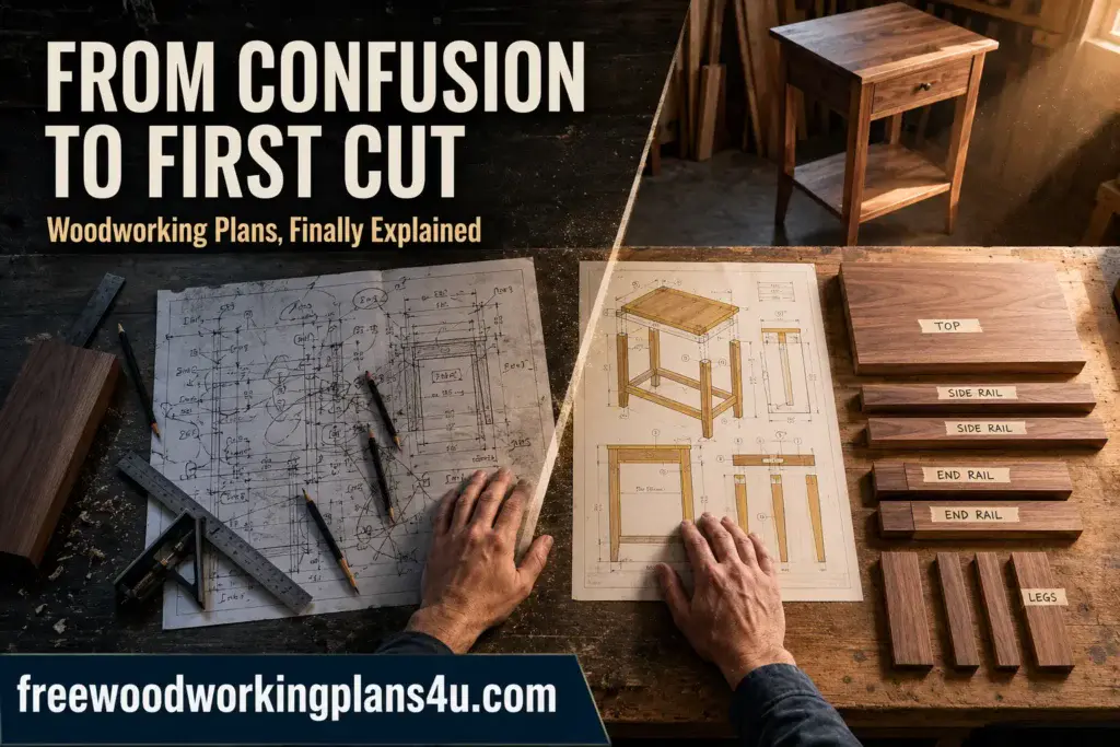
Understanding woodworking plans means knowing what the page tells you—and noticing what it has not told you yet.
When the Numbers Refuse to Behave
Sometimes you are missing a detail. Sometimes the detail is hidden elsewhere. Occasionally, the plan is wrong.
Do not choose an answer because it seems close enough.
Ask Whether the Answer Is Somewhere Else
Compare the:
- Cut list
- Main drawings
- Section views
- Detail drawings
- Written instructions
- Photographs
- Hardware list
- Templates
- Notes and legend
A missing width may appear in a section. A photograph may settle an orientation question. The written step may explain why a part is intentionally left long.
Look for the Geometry You Cannot See
Apparent errors may be explained by:
- Dados
- Rabbets
- Tenons
- Overhangs
- Inset backs
- Face frames
- Applied trim
- Gaps and reveals
- Nominal lumber sizes
A shelf can be longer than the visible opening because its ends enter dados. A back panel can be smaller than the cabinet because it fits inside a rabbet.
Build the Question in Cardboard
A full-size mock-up can resolve uncertainty faster than another hour of staring at the plan.
Use cardboard, foam board, scrap plywood or inexpensive lumber to test:
- Overall proportions
- Seat height
- Backrest angles
- Drawer placement
- Door swing
- Hardware clearance
- Reach and comfort
- Whether the completed project can pass through a doorway
A mock-up has no need to impress anyone. Its job is to expose trouble while the consequences are still cheap.
Calculate Only What the Known Dimensions Can Prove
Suppose a shelf fits between two 3/4-inch sides in a 30-inch-wide cabinet:
30 − 3/4 − 3/4 = 28 1/2 inches
That answer works only if:
- Thirty inches is the true outside width
- Both sides actually measure 3/4 inch
- The shelf fits directly between them
- No dado, rabbet or overlapping part changes the relationship
Write calculated dimensions in another color. Keep assumptions visible until they have been confirmed.
Ask the Designer a Question They Can Answer
When possible, include:
- Project name
- Page or step number
- Part labels
- Conflicting measurements
- A photograph or screenshot
- Your current interpretation
“The dimensions for Part C differ between the cut list and Detail 4” is far easier to answer than “the plan does not make sense.”
Know When Uncertainty Is Not Yours to Improvise Around
Do not guess when the unresolved detail affects structural loads, stairs, guardrails, elevated platforms, children’s furniture or other safety-critical work. Seek qualified guidance and follow applicable requirements.
A woodworking plan also does not replace the operating manual for a power tool. Follow the manufacturer’s instructions for setup, blades, bits, guards, work holding and protective equipment. OSHA’s woodworking safety resources provide useful general hazard information, but your specific equipment manual remains essential.
Resizing the Project Without Quietly Weakening It
A plan may look easy to modify. Add six inches here. Remove two inches there.
But dimensions are connected.
Lengthening a table increases the unsupported span. Widening a cabinet may require a center divider or thicker shelf. Changing plywood thickness can alter dados, drawers, doors and hardware clearances.
Before changing anything, sort the dimensions into five groups.
Overall Dimensions
These define the outside of the project:
- Height
- Width
- Depth
They are usually the values you want to change.
Structural Dimensions
These influence strength and stiffness:
- Leg thickness
- Apron width
- Shelf thickness
- Unsupported span
- Stretcher size
- Joinery length
- Fastener size
These cannot always be enlarged or reduced by the same percentage as the overall project.
Fit Dimensions
These control mating or moving components:
- Drawer clearances
- Door gaps
- Hardware spacing
- Slide allowances
- Lid clearance
- Shelf fit
- Panel expansion space
A difference of 1/16 inch can matter here.
Joinery Dimensions
These include:
- Dado width and depth
- Mortise dimensions
- Tenon thickness
- Dowel diameter
- Screw length
- Pocket-hole settings
Joinery often depends on material thickness rather than the overall size of the project.
Recommended reading: The 25 Best Woodworking Joinery Books Every Woodworker Should Own (From Beginner to Master Craftsman)
Material-Controlled Dimensions
These are dictated by what you actually bought:
- Plywood thickness
- Board width
- Milled hardwood thickness
- Hardware dimensions
- Drawer-slide requirements
After modifying the design:
- Redraw the critical assemblies.
- Recalculate every dependent dimension.
- Produce a clean cut list.
- Check the hardware.
- Reconsider the structure.
- Repeat the full pre-cut audit.
A page buried beneath crossed-out numbers is not a revised plan. It is a misunderstanding waiting for the right afternoon.
Choosing a Plan That Will Not Leave You Stranded
A beginner-friendly plan is not merely a plan for a small project. It is a plan that removes unnecessary uncertainty.
Reassuring Signs
Look for:
- Clear finished dimensions
- A complete materials list
- A separate hardware list
- A labeled cut list
- Multiple drawing views
- Exploded diagrams
- Enlarged joint details
- Ordered instructions
- Tool and skill requirements
- Notes around critical measurements
- Photographs of important stages
- Consistent dimensions from page to page
Reasons to Slow Down
Be cautious when you find:
- Beautiful photographs with very few measurements
- Unlabeled components
- No finished size
- Missing material thicknesses
- A cut list that conflicts with the drawings
- Joinery without dimensions
- Mirrored parts that are not identified
- Vague hardware specifications
- An impossible assembly order
- No allowance for solid-wood movement
- Unexplained dependence on specialized tools
Free Plans and Paid Plans Must Pass the Same Test
A price tag does not verify a drawing.
Some free woodworking plans are complete, tested and thoughtfully illustrated. Some paid plans quietly ask the builder to fill in missing information.
Before trusting either, ask:
- Can I identify every component?
- Are the finished dimensions clear?
- Does the cut list agree with the drawings?
- Is the joinery explained?
- Can I follow the assembly sequence?
- Do I have the required tools and skills?
- Are material-dependent measurements identified?
- Can every important question be resolved before cutting?
A good first plan does not need to be embarrassingly simple. It needs to be clear enough that your attention can stay on the craft instead of reconstructing the designer’s intentions.
The Questions That Usually Surface at the Workbench
“Where am I supposed to start when I open the plan?”
Start with the finished image and the overall height, width and depth. Identify the front, sides, top and major assemblies. The individual pieces will make more sense once you understand the object they are trying to become.
“Aren’t the materials list and cut list basically the same thing?”
No. The materials list tells you what raw lumber, sheet goods, hardware and supplies to purchase. The cut list divides that stock into individual project components with quantities and dimensions.
“Do all woodworking plans use the same symbols?”
Many drawing conventions are widely recognized, including dashed hidden lines, centerlines, diameter symbols and section hatching. Designers still vary, so always check the legend and notes included with the plan.
“What are those dashed lines trying to show me?”
Dashed lines usually represent an edge, hole, joint or component hidden behind a visible surface. A section or detail view may reveal exactly what lies there.
“What does TYP mean—and how far does it apply?”
TYP means “typical.” The note applies to equivalent repeated features unless another instruction says otherwise. It does not automatically apply to every similar-looking detail.
“How do I know I’m reading the cut list correctly?”
Begin with the column headings. Identify the part label, name, quantity, thickness, width, length and material. Then match every row to the drawings and confirm that its dimensions and quantity fit the completed assembly.
“Can I trust the cut list?”
Use it as a primary reference, but verify it against the drawings, instructions and finished dimensions. Plans can contain errors, and some parts must be sized from the actual assembly.
“Why don’t these measurements add up?”
Look for nominal lumber sizes, plywood thickness, overhangs, dados, rabbets, tenons, inset components and gaps. Trace the endpoints of the dimension lines. If the relationship still fails, treat it as unresolved rather than choosing the number you prefer.
“Should I cut every part now and get it over with?”
Only when the dimensions are fixed. Repeated structural components can often be cut together. Shelves, drawers, doors, backs, stretchers and trim may fit better when measured from a dry-assembled project.
“Can I measure the picture if one dimension is missing?”
Not unless the drawing is explicitly identified and verified as full size. Website images, PDFs and printed pages may all be resized. Use written dimensions or calculate the missing value from confirmed relationships.
“How do I know which face gets the joint?”
Match the component across the front, side, top, exploded and detail views. Mark its front, back, inside, outside, top and bottom before cutting.
“What kind of plan should I choose for my first project?”
Look for square construction, common materials, a manageable number of parts, clear diagrams, a labeled cut list and simple joinery. Boxes, shelves, benches and basic tables can be excellent choices when the instructions are complete.
“Can I make the project larger or smaller?”
Usually, but resizing can affect structure, joinery, material quantities, hardware and component fit. Recalculate every dependent dimension and create a revised cut list before cutting.
“How can I tell whether the plan is accurate?”
Check that every listed component appears in the drawings, every drawn component appears in the cut list, quantities are correct and the parts reconcile with the finished dimensions. Test unfamiliar joints and hardware on scrap.
“Do I need to learn technical drafting first?”
No. Begin with the core language: drawing views, dimension lines, symbols, sections, materials, cut lists and assembly relationships. More advanced drafting knowledge can grow naturally as your projects become more complex.
“What if two dimensions contradict each other?”
Stop and compare the cut list, main drawings, details and written instructions. Determine whether one number is nominal, material-dependent or affected by a joint. If the contradiction cannot be resolved confidently, contact the designer or use another plan.
Products / Tools / Resources
Understanding the plan happens mostly in your head, but a few uncomplicated tools make that work calmer and far more precise.
A Working Copy You Are Willing to Mark
Keep the original plan clean. Print another copy—or duplicate the digital file—and treat that version as part of the workshop.
Highlight critical dimensions. Check off completed parts. Record actual plywood thickness. Circle irreversible steps. Write questions directly beside the confusing detail.
A pristine plan is less valuable than one that has helped you think.
A Tape Measure You Know Instinctively
Choose a tape with crisp markings you can read without hesitation. Familiarity matters. Switching between different tapes during the same project can introduce small discrepancies, particularly when hooks and printed scales differ slightly.
Use the same tape for related measurements whenever possible.
A Steel Rule for Short, Exact Layouts
A flexible tape is useful across a cabinet or tabletop. A steel rule feels more dependable when marking small offsets, checking hardware or laying out joinery.
Its edge stays flat. The marks remain close to the work. There is less room for the blade to bow or wander.
A Combination Square
A combination square earns its place beside almost every plan.
Use it to:
- Establish reference faces
- Draw square layout lines
- Transfer measurements
- Mark repeated offsets
- Check 90-degree assemblies
- Confirm consistent joint locations
Before relying on it, verify that the square is actually square.
A Digital or Dial Caliper
A caliper answers the question the label cannot: how thick is this material really?
It is particularly useful for measuring:
- Plywood
- Dowels
- Drill bits
- Hardware
- Groove width
- Tenon thickness
- Small gaps and clearances
For fitted joinery, that information can be the difference between a clean fit and a joint that rattles.
Fine Mechanical Pencils and Colored Pencils
Use a fine pencil for layout and another color for calculated or modified measurements.
A simple color system can separate:
- Original plan dimensions
- Your calculations
- Corrected values
- Material-dependent measurements
- Questions that still need answers
That separation becomes surprisingly valuable once the project has occupied several evenings.
Painter’s Tape for Part Labels
A small piece of painter’s tape can carry a part number, orientation and reference face without leaving a permanent mark.
Label parts immediately. Do not trust yourself to remember which nearly identical board was the front-left leg after you have moved them around the bench three times.
Scrap From the Actual Project
Keep useful offcuts nearby.
Use them to test:
- Dado width
- Rabbet depth
- Pocket-hole settings
- Drill depth
- Screw length
- Hardware fit
- Stain color
- Finish compatibility
Scrap taken from the same stock tells you more than an unrelated board because its thickness, grain and behavior match the project.
A Fraction Chart and Basic Calculator
A fraction-to-decimal chart can untangle plans that mix fractions, decimals and metric dimensions. A calculator helps with repeated spacing, resizing and component totals.
Write every calculated dimension onto the working copy, then check it a second time before carrying it to the wood.
Safety Equipment Matched to the Work
The plan may mention the project tools without describing every protective measure they require.
Depending on the operation, appropriate equipment may include:
- Safety glasses
- Hearing protection
- Dust protection
- Push sticks or push blocks
- Clamps
- Featherboards
- Tool guards
- Adequate lighting
Use the manufacturer’s instructions for your specific tools, blades and accessories.
Learn more: Build a Safer Workshop: The Ultimate Beginner-to-Pro Woodworking Safety Equipment Roadmap
Clear Plans Worth Practicing With
The easiest way to become comfortable with woodworking plans is to use them.
Choose projects with finished dimensions, labeled cut lists, multiple drawing views, clear joinery details and an assembly sequence that does not leave you filling in the missing steps.
These 27 free beginner woodworking plans offer practical places to begin, while beginner plywood projects can be especially approachable when you want stable, readily available material and straightforward construction.
For a larger collection to study and build from, get 50 FREE Woodworking Plans plus “The Art of Woodworking,” a 440-page woodworking guide.